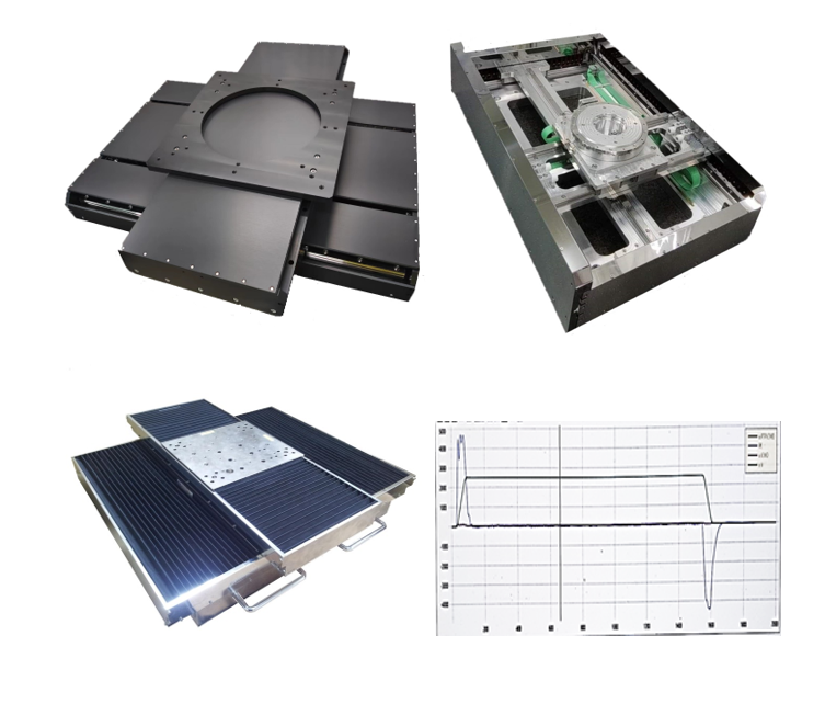
Ultra precision positioning stage has been our core technology for 17 years. The technology was first transferred from NSK. Then the cooperation with Taiwan semiconductor industry further enhances our company’s capability to be the world-wide solution provider. This series mainly compose three models.
- Positioning stage for general purpose
- Positioning stage for line scan application
- Positioning stage for ultra vacuum application
There are various size for selection. The tailor-made request is also acceptable.
[Go to download…]
Applications
- Isolation layer hole drilling for wafer probe card
- E-beam inspector for semiconductor
- Wafer boding equipment
- Line scan AOI wafer inspection machine
- LCD/LED die bonder, wire bonder, and sorter
etc…
Positioning stage for general purpose
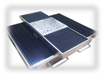
- Extremely low cogging linear motor is employed to reduce settling time and enhance trajectory tracking.
- NSK precision linear guide is adopted for best performance.
- 50 nm stepping and repeatability of ±0.3umcan be realized.
- Miniature optical encoder and programable resolution interpolator is used to ease application.
- Bellow cover is used to achieve dust proof.
-
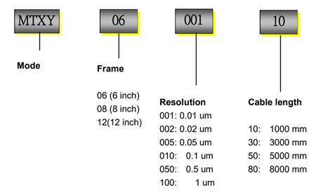
Model designation:
-
Specification:
| Mechanical parameters | Unit | MTXY06 | MTXY08 | MTXY12 |
| Total stroke | mm | 170 | 220 | 320 |
| Effective stroke | mm | 160 | 210 | 310 |
| Straightness | um | <2 | <2.5 | <3 |
| Flatness | um | <8 | <12 | <15 |
| Repeatability | um | ±0.3 | ±0.3 | ±0.3 |
| Accuracy | um | <0.6 | <0.6 | <0.6 |
| Moving mass of upper axis | kg | 7 | 7 | 7 |
| Moving mass of lower axis | kg | 19 | 21 | 24 |
| Maximal payload | kg | 20 | 20 | 20 |
| Electrical parameters | Unit | |||
| Peak force of upper axis | Nt | 720 | 720 | 720 |
| Peak force of lower axis | Nt | 1200 | 1200 | 1200 |
| Conti. Force of upper axis | Nt | 240 | 240 | 240 |
| Conti. Force of lower axis | Nt | 400 | 400 | 400 |
| Peak current of upper axis | Arms | 16.8 | 16.8 | 16.8 |
| Peak current of lower axis | Arms | 19.2 | 19.2 | 19.2 |
| Conti. current of upper axis | Arms | 5.6 | 5.6 | 5.6 |
| Conti. current of lower axis | Arms | 6.4 | 6.4 | 6.4 |
| Force constant of upper axis | Nt/Arms | 42.5 | 42.5 | 42.5 |
| Force constant of lower axis | Nt/Arms | 63.4 | 63.4 | 63.4 |
| Pole pair pitch | mm | 27 | 27 | 27 |
| Motor voltage | VAC | 220 | 220 | 220 |
-
Dimensions:
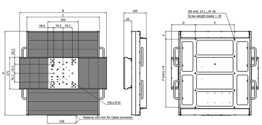
| Stroke (mm) | Dimensions- mm | ||||||||
| Upper axis | Lower axis | A | B | C | D | E | F | P(mm)xN | |
| 160 | 160 | 552 | 552 | 480 | 174 | 204 | 58 | 145 x 3 | |
| 210 | 210 | 602 | 602 | 510 | 184 | 234 | 83 | 145 x 3 | |
| 310 | 310 | 712 | 712 | 594 | 197 | 318 | 66 | 145 x 4 | |
Positioning stage for line scan application
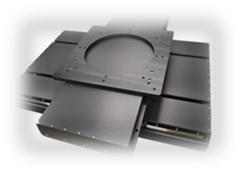
- Zero cogging linear motor is employed to achieve the best velocity stability.
- NSK precision linear guide is adopted for best performance.
- Repeatability of ±0.2um and velocity stability of 0.2% @ 250mm/s can be realized.
- Black anodized surface treatment is adopted to eliminate light interference.
- 48VDC is adopted for motor drive to prevent velocity stability and image acquisition from AC power noise.
- Miniature optical encoder and programable resolution interpolator is used to ease application.
-
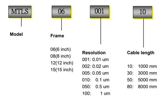
Model designation:
-
Specification:
| Mechanical parameters | Unit | MTLS06 | MTLS08 | MTLS12 | MTLS15 |
| Total stroke | mm | 170 | 220 | 320 | 400 |
| Effective stroke | mm | 160 | 210 | 310 | 380 |
| Straightness | um | <1 | <1.5 | <2 | <2.5 |
| Flatness | um | <4 | <6 | <8 | <10 |
| Repeatability | um | ±0.2 | ±0.2 | ±0.2 | ±0.2 |
| Accuracy | um | <0.5 | <0.5 | <0.5 | <0.5 |
| Moving mass of upper axis | kg | 8 | 8 | 8 | 8 |
| Moving mass of lower axis | kg | 20 | 23 | 28 | 34 |
| Maximal payload | kg | 10 | 10 | 10 | 10 |
| Electrical parameters | Unit | ||||
| Peak force of upper axis | Nt | 246 | 246 | 246 | 246 |
| Peak force of lower axis | Nt | 492 | 492 | 492 | 492 |
| Conti. Force of upper axis | Nt | 52 | 52 | 52 | 52 |
| Conti. Force of lower axis | Nt | 104 | 104 | 104 | 104 |
| Peak current of upper axis | Arms | 19 | 19 | 19 | 19 |
| Peak current of lower axis | Arms | 38 | 38 | 38 | 38 |
| Conti. current of upper axis | Arms | 4 | 4 | 4 | 4 |
| Conti. current of lower axis | Arms | 8 | 8 | 8 | 8 |
| Force constant of upper axis | Nt/Arms | 13 | 13 | 13 | 13 |
| Force constant of lower axis | Nt/Arms | 13 | 13 | 13 | 13 |
| Pole pair pitch | mm | 45 | 45 | 45 | 45 |
| Motor voltage | VDC | 48 | 48 | 48 | 48 |
-
Dimensions:
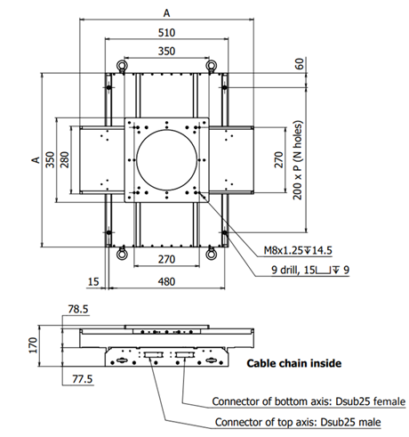
| Stroke (mm) | Dimensions- mm | ||
| Upper axis | Lower axis | A | P x N |
| 160 | 160 | 510 | 2 x 3 |
| 210 | 210 | 550 | 2 x 3 |
| 310 | 310 | 650 | 3 x 4 |
| 380 | 380 | 720 | 3 x 4 |
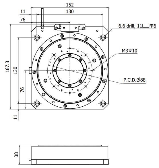
Positioning stage for ultra vacuum application
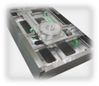
- Zero cogging linear motor is employed to achieve the best velocity stability.
- NSK precision linear guide is adopted for best performance
- 50 nm stepping and repeatability of ±0.3umcan be realized.
- All windings are stationary to solve heat dissipation problem in the vacuum.
- A novel decoupling mechanism is adopted so that the band width and motor parameters are the same for both axes.
- Miniature optical encoder and programable resolution interpolator is used to ease application.
-
Model designation:
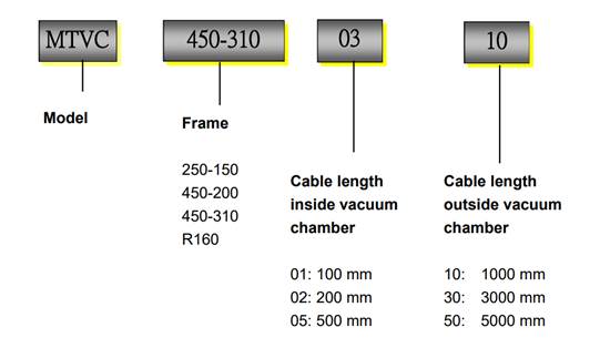
-
Specification:
| Mechanical parameters | Unit | 250-150
|
450-200 | 450-310 | R160
Rotary DD |
| Total stroke | mm | 260/160 | 460/210 | 460/320 | 360 |
| Effective stroke | mm | 250-150 | 450/200 | 450/310 | 360 |
| Straightness | um | <2 | <2 | <2 | <2.5 |
| Flatness | um | <5 | <5 | <5 | <5 |
| Repeatability | um | ±0.3 | ±0.3 | ±0.3 | ±1 arcsec |
| Accuracy | um | <0.8 | <0.8 | <0.8 | <3 arcsec |
| Moving mass of upper axis | kg | 7 | 7 | 7 | 4618
Kg-mm^2 |
| Moving mass of lower axis | kg | 7 | 7 | 7 | |
| Maximal payload | kg | 20 | 20 | 20 | 20 |
| Electrical parameters | Unit | ||||
| Peak force of upper axis | Nt | 190 | 190 | 190 | 2.7
Nt-m |
| Peak force of lower axis | Nt | 190 | 190 | 190 | |
| Conti. Force of upper axis | Nt | 63 | 63 | 63 | 0.9
Nt-m |
| Conti. Force of lower axis | Nt | 63 | 63 | 63 | |
| Peak current of upper axis | Arms | 15 | 15 | 15 | 4.8 |
| Peak current of lower axis | Arms | 15 | 15 | 15 | |
| Conti. current of upper axis | Arms | 5 | 5 | 5 | 1.6 |
| Conti. current of lower axis | Arms | 5 | 5 | 5 | |
| Force constant of upper axis | Nt/Arms | 13 | 13 | 13 | 0.56
Nt-m/Apeak |
| Force constant of lower axis | Nt/Arms | 13 | 13 | 13 | |
| Pole pair pitch | mm | 45 | 45 | 45 | 12 poles |
| Motor voltage | VDC | 48 | 48 | 48 | 48 |
-
Dimensions:
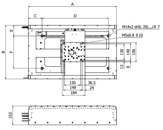
| Stroke (mm) | Dimensions- mm | ||||||
| Frame | Upper/lower | A | B | C | D | E | F |
| XY250-150 | 250/156 | 481 | 381 | 65.5 | 350 | 85.5 | 210 |
| XY450-200 | 450/206 | 711 | 431 | 110.5 | 535 | 85.5 | 260 |
| XY450-310 | 450/316 | 711 | 541 | 100 | 545 | 85.5 | 370 |
Download
[Back to top…]
| Item | Filename | Remark |
| Ultra precision positioning stage | Ultra precision positioning stage.pdf | |
| MTXY06 | MTXY06.stp | 3D |
| MTXY08 | MTXY08.stp | 3D |
| MTXY12 | MTXY12.stp | 3D |
| MTLS06 | MTLS06.stp | 3D |
| MTLS08 | MTLS08.stp | 3D |
| MTLS12 | MTLS12.stp | 3D |
| MTLS15 | MTLS15.stp | 3D |
| MTVC250-150 | MTVC250-150.stp | 3D |
| MTVC450-200 | MTVC450-200.stp | 3D |
| MTVC450-310 | MTVC450-310.stp | 3D |
| MTVCR160 | MTVCR160.stp | 3D |